| Stripping steam regeneration system by combined 3-stage MVR & TVR |
|
A number of strippers are in opereation in the down stream of polymerization process producing polymers in many petrochmical plants. The polymers containing residual monomers are stripped by steam to vaporize and condense into aqueous mixture for subsequent recoevry to pure monomers to recyle back to the polymerization. In this process, a big mass of stripping steam is consumed and cooling water to condenser is circulated.
We deveolped the "Stripping steam regeneration system" incorporated with MVR and TVR. |
|
|
|
Descriptions |
Unit |
1 |
2 |
3 |
4 |
5 |
6 |
Phase |
|
vapor |
liquid |
vapor |
vapor |
vapor |
vapor |
Mass flow rate |
kg/h |
39,300 |
6,432 |
5,900 |
6,432 |
6,378 |
12,810 |
Temperature |
℃ |
93 |
70 |
79 |
107 |
180 |
120 |
Pressure |
㎏/㎠G |
0.45 |
1.5 |
- 0.536 |
0.33 |
9 |
1.04 |
MVR coupling power |
KWh |
|
|
275 |
|
|
|
The basic engineering of this system inquired us to maximize a heat recovery from the stripper overhead vapor and to optimize mass flow rate and pressure of the regenerated stripping steam to reuse for the stripper. The best optimized balance is calculated as a result as per the above table. The most important target is to get the stripping pressure of 1.04 ㎏/㎠G that is not possible by 3-stage turbo blower only, thus TVR is incorporated for a further compression by consuming high pressure motive steam being added to match to the required mass flow rate of 12,000 kg/h for the stripper. By this optimizing conditions, the enthalpy recovery rate is achieved to approximately 50%.
The stripper overhead vapor consisted of cyclo-hexane, n-heptane and water flows into a plate type wide gap condensing evaporator to be condensed in hot side and to evaporate hot water in cold side. This unique application is to provide easy cleaning of polymer deposit on the hot side periodically. The hot water is supplied to cold side plates gap where vacuum is maintained to evaporate the steam at lower temperature than the condensing temperature at hot side.
Uncondensed vapor shall be condensed at lower temperature in the existing condenser and vapor condensate will join in the decanter where hydrocarbons and water are separated by gravity. 3-staged MVR compresses this vacuum steam adiabatically to discharge with an elevated pressure, super heated which is desuperheated by condensate injection to get the saturated steam. We are exclusively using inverter controlled turbo fan as MVR instead of guide vane controlled turbo compresser because of it's easy operation and maintenance charactoristics owing to low speed. |
|
| The right photo shows 3-stage MVR & TVR system regenerating heat from the stripper overhead vapor in the butadiene rubber plant installed in 2008. 3-stage MVR are installed in parallel on the structure of 15 M above the ground. Turbo fan type MVR is less sensitive than compresser on the vibrating atmosphere that positioning on a upper structure would be possible to assure the vibration sacle of 3∼10㎛. |
|
|
|
| Stripping steam regeneration system by 4-stage MVR |
|
Thanks to a successful operation of the first installed system, the second order was received to start operation in January, 2010. Composition of the stripped vapor containing n-heptane, cyclo-hexane, toluene with water and higher temperature allowed us to use 4-stage MVR without second compression by TVR, however, a presence of toluene declining to take the plate evaporator with gaskets and very low delta-T to attain high evaporation rate to reach the demand of stripping steam without an aid of TVR stimulates us to develop our first horizontal falling film evaporator having extremely large syrface. It will be the first project in the world installing 4-stage MVR turbo fan in series elevating 35℃ . By this extensive study, we could expect a enthalpy recovery rate higher than 90% of the stripped vapor. |
|
|
|
Descriptions |
Unit |
1 |
2 |
3 |
4 |
|
|
Phase |
|
vapor |
liquid |
vapor |
vapor |
|
|
Mass flow rate |
kg/h |
45,890 |
13,000 |
13,000 |
14,277 |
|
|
Temperature |
℃ |
102 |
90 |
88 |
123.3 |
|
|
Pressure |
㎏/㎠G |
0.7 |
1.5 |
- 0.387 |
1.24 |
|
|
MVR coupling power |
KWh |
|
|
800 |
|
|
|
|
 |
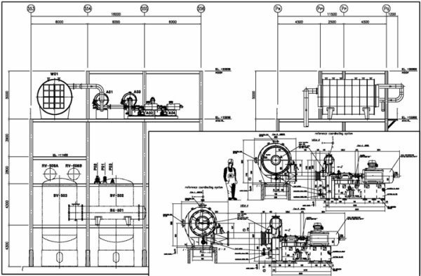
The drawing on the top shows the horizontal tube falling film evaporator and 4-stage MVR are on 15.3 M level and the existing condenser on 4.3 M level and the strippers are on the ground. A circulation and vacuum pumps are located on 8.6 M level.
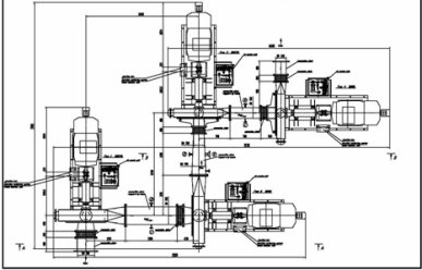
The right drawing shows a layout of 4-stage MVR which is different from |
|
 |
|
| 3-stage MVR in parallel permitting a certain turbulent flow of vapor between each stage. They are positioned in such a way to minimize turbulent flow between the stages and avoid vibrating resonance of the system. |
|
| |


